Power Equipment Forum banner

Coleman Powermate 6250 not generating power.

20K views 39 replies 7 participants last post by  jomar1647  
#1 ·
Hi Forum,

I have a Problem with my Powermate 6250 Generator. I usually pull it out every 4 month and let it run for a while. Last time I used it to vacuum my car and all the sudden it stopped producing power.

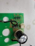
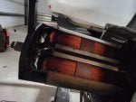
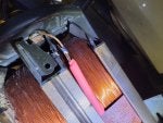
I checked the brushes and they are not brand new, but also not worn. I can measure the length tonight.
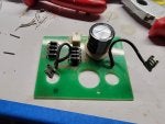
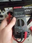
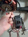
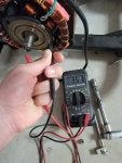
I also removed the black end cap and saw that the brushed are just connected to a few diods and capacitor. I measured the diods and they are fine. I also measured the resistance of the rotor and believe that it's also fine. I can't really say anything to the capacitor, but it looked ok, not blown or so.

Now, when I used the vacuum it felt like, the vacuum cleaner started to run slower and slower while it was connected to the Generator. The RPM of the Generator where constant.

I found this website and followed the repolarizing section. Fixing Electrical Problems in Coleman Powermate Generators

It makes a good sparc, but still does not produce power. If I connect a jig saw to the outlet and switch it on while I am repolarizing the Generator and leave the battery connected to the brushes the jig saw starts to slowly moving. In a way as it would run on 10% of the full speed the jig saw can do. So I think my Generator is technically ok, but I don't know how to get it working again.
Image
 
#4 ·
It looks like it's from around 2004.

Some things to check when a generator won't provide power: Make sure the breakers are not tripped and are in good condition. Also, the AVR could be bad. The biggest problem you're going to have is that a lot of parts are no longer available for generators of that vintage.
 
#5 ·
Ok, so I worked a bit on it again. It´s a PM0525303. I dissasambled the back of the generator again and measured the length of the brushes. See attached pictures, I am sure the brushes are ok. I also measured the coils, I have around 1.5Ohm. Is that correct?

When I tried to repolarized the Generator I wasn´t quite sure where to connect plus and minus and I may have done it wrong. See picture of the burned pcb borad. I fixed it with a short cable.

Does someone know: Are that 8 diods on the PCB board?? I would think yes and last time when I measured them I had 0 ohm in one direction and high ohm in the other. If I measure them now I found from the 2 x 4 groups the both inside having 0 ohm and 620ohm, the two outside have 0 ohm in both directions. I might have fried them??
Image

Image
Image
Image
Image
Image
Image
Image
Image
 
#8 ·
Does someone know: Are that 8 diods on the PCB board?? I would think yes and last time when I measured them I had 0 ohm in one direction and high ohm in the other. If I measure them now I found from the 2 x 4 groups the both inside having 0 ohm and 620ohm, the two outside have 0 ohm in both directions. I might have fried them??
Yes, there are 8 diodes on the board. I see that the trace has been blown off the board (which you repaired with a jumper). So something went terribly wrong. Could have happened if you connected your 12V source backwards.
You could try the diode test setting (it has the diode symbol) on your meter. The diode should indicate continuity in only one direction. If you have to replace them, that looks like a RL205 diode which is 2A, 600V. Just search eBay or Amazon.
 
#6 ·
Check the resistance of the main stator because from the looks of it, it may have been overloaded at some point. See the lacing around it? Tell tale signs of overheating would be a cut or burnt lacing. Look for discoloration as well... windings that are darker compared to others around it would indicate overheating.

If you look closely, there's a line of winding near where the lacing was cut in the left box that seems discolored.

Either that or it's just an aberration in the picture.

Image
 
#9 ·
Yeah, user error. I tried both directions for recharging it. I tried the diode setting first and had a reading for 620Ohm in one direction and 0 in the other for the ones outside, for the inside I had a reading of 0 and 0 both directions. So they should be damaged I guess. I just looked on mouser, the RL205 is discontinued, I just use a 600V 3A through hole and will replace all of them. https://www.mouser.com/ProductDetail/Comchip-Technology/1N5406-G?qs=2qJf6qQ4IOKM5wnaBCciuQ==

Is there anywhere an explanation how this board works - an electrical diagram? I am sure they did not reinvent the wheel...

I also measured the coils of the stator. They are around 0.5 Ohm. Detailed pictures as well attached.

Image
Image
Image
Image
Image
Image
Image
 
#12 ·
The stator is toast, IMO. There clearly are burn marks where the lacings were severed. The insulation has been compromised so frankly, it's not a question of whether it will still work or not, but rather of safety.

The exciter circuit burning out could just be a symptom of the issue with the stator.
 
#13 · (Edited)
yes, electrolytic capacitor could have been ruined, the entire board is very simple.
But it was not working so you 'repolarized', reverse polarity on electrolytic caps ruins them.
Popping a Capacitor Video: What Not to do With Caps (jameco.com)
DC electrolytic capacitors are polarized by the manufacturing process and therefore can only be operated with DC voltage. Voltages with reverse polarity, or voltage or ripple current higher than specified can destroy the dielectric and the capacitor. The destruction of electrolytic capacitors can have catastrophic consequences such as a fire or an explosion. If a polarized capacitor is installed incorrectly, the capacitor whistles then explodes.

However it does not look popped, they really do explode into bits.
I am also suspicious of the diodes, you said they read zero ohms both ways?
And the diode test function is useful but ganged diodes, not sure if that changes the reading you get from them, for the voltage drop test probably does, but zero ohms both ways tells you they are shorted.
All those parts are pretty cheap.
How to Test Diodes with a Digital Multimeter | Fluke
The stater, I cant see the problem OrlyP is talking of.
 
#16 ·
Is there another system control board in this gen set?
No, the top part outside of the motor is just the fuses and outlets. No fruther electronic. I may take a picture if I open that area again. The generator has no AVR as far as I see it. It´s a real simple electric and mechanic design. The rpm controll is done by a govenor. I installed a hal sensor, RC servo and a mircocontroler to controll the carburator opening/rpm a few years back. the RPM was super stable no matter of the load!! It worked fine, but I later needed the parts for other stuff. LOL. I never really used the Generator long term, it´s for hurricanes, but we haven´t seen on in years.
Image


I guess nobody wants to talk about the elephant in the room. To me, the exciter circuit is going to be the least of your problems. Here's another picture showing the damage on the stator. Note that the marks I've drawn are just the obvious faults visible in the picture. There are burnt and discolored windings pretty much all over.

Now, it's up to you if you want to put the cart in front of the horse but, with a stator like that, you'll probably end up trashing the new/refurbished/repaired exciter circuit as soon as you power it up.
Just a fair warning.
I see that the lacings are damaged, but I inspected the area again and I can´t really see what you see on the pictures. To me it looks normal. Are you concerned the coil has contact to the housing or the coil itself has a short cut in itself = the current would pass less windings as necessary.

I am also suspicious of the diodes, you said they read zero ohms both ways?
Correct. I ordered new diods from mouser and will replace all of them. Regarding the capacitor, even if it would explode, it´s well covered in the housing. I am concerned of a fire hazared even with a brand new generator. In my opinion most generators are cheaply build and I would not trust them being anywhere close my house.

It will be probably the weekend until I get the new diods and can test it again.
 
#15 ·
I guess nobody wants to talk about the elephant in the room. To me, the exciter circuit is going to be the least of your problems. Here's another picture showing the damage on the stator. Note that the marks I've drawn are just the obvious faults visible in the picture. There are burnt and discolored windings pretty much all over.

Now, it's up to you if you want to put the cart in front of the horse but, with a stator like that, you'll probably end up trashing the new/refurbished/repaired exciter circuit as soon as you power it up.

Just a fair warning.

Image
 
#19 ·
Took me a bit longer, but today I was able to test it. The generator is not creating power after regular start.

I tried the Repolarizing. I used an lod light bulb to as a current limiting resistor. Connected - to the left and + to the right. I measured the current in the repolarizing ciruit and it was around 0.8A at 12V. Still no power. I repeated that quite often and still no power. I removed after that the light bulb and measured around 8-10A at 12V.Still no power...

I connected a jig saw to one of the outlets switched it on and tried it again. Same behaeviour as before, the jig saw runs on sort of low Rpm as long as I hold the 12V to the brushes but stops after that.

So in general the Generator is working, but something is weird with the repolarization I guess.

Should I try to use a higher voltage like 24V for the repolarization?
 
#20 · (Edited)
This is somewhat in your ballpark....


TL;DW: Re-check all resistance readings:

Typical values of what you should get are given for the generator in the video. Yours may vary a little due to it's slightly different kW capacity.

Part 1: Windings
1. Leg1 Hot to Neutral: ~0.4 Ω
2. Leg2 Hot to Neutral: ~0.4 Ω
3. DPE (yellow wires, rectifier disconnected): ~1.5 Ω
4. Rotor (measure directly on slip rings without brushes): ~30 Ω
5. Rotor (measure through the brushes, rectifier disconnected): ~32 Ω

Part 2: Ground Fault
Measure Leg1 to Ground: OL
Measure Leg2 to Ground: OL
Measure DPE to Ground: OL
Measure Rotor slip rings to rotor shaft: OL

In the video, he was getting around 120V DC across the brushes. But due to the several issues (blown cap, dirty slip rings), he initially was only getting ~70V DC.
 
#21 ·
Wow, that was super helpful. I measured the OL everywehere exept from the rotor slit ring to the rotor shaft. See pictures below. There must be a short cuit on the inner ring.

Also I had 47Ohm over the slip ring and brushes, before I cleaned them. After cleaning it lowered to 35Ohm.
 

Attachments

#23 ·
make sure to use a good fluke meter to do the low OHM testing.
most other meters will just get you at go - no go...

you need exact on the ohms as most readings you need are in 100ths of an ohm.
but a tenth of an ohm will get you close...
 
#27 ·
Well, I wanna say, I think I found and repaired the issue. See belows pictures. I resodered the connection, put heat shrint about it and feeded the able through a new way. Measureaments are ok now. Will test tomorrow.
 

Attachments

#28 ·
Wow! It looks like your luck just turned for the better! Go buy some stock right now! :)

Make sure you secure that very well. There is a lot of centrifugal force that will want to throw that wire outward.
 
#29 ·
There you go.... you're halfway through.

You will need to secure that wire with epoxy or some other means to securely hold it in place. That rotor is doing 3600 RPM and that length of wire will easily fly outwards and cause some further damage.
 
#31 ·
That's got to be some really strong glue.

The edge of the black plastic near the slip rings seems mangled up. I believe that's where the winding was originally secured to but then a strand of winding went off and snagged the stator, pinching it against the rotor core and scraping off the insulation. It's a wonder that the damage isn't so much more severe.
 
#32 ·
Not only strong glue but also heat resistant. A lot of glues tend to soften with heat.

Take a look at the stator while you have the rotor out because there might be some damage to the stator that needs to be addressed. Something was in there that made those marks on the rotor.
 
#33 · (Edited)
There are adhesives specifically designed to secure windings on generators and motors. You will need to use that.

I think a brand called Permabond makes some.

It may also be prudent to give the rotor a good varnish coating or bath. This helps to reinforce the insulation and prevent any part of the winding from unraveling while in operation.